Capacitor
A capacitor is a passive two-terminal electrical component used to store energy electrostatically in an electric field. The forms of practical capacitors vary widely, but all contain at least two electrical conductors (plates) separated by a dielectric (i.e., insulator). Capacitors are widely used as parts of electrical circuits in many common electrical devices. Unlike a resistor, a capacitor does not dissipate energy. Instead, a capacitor stores energy in the form of an electrostatic field between its plates.
Capacitance is expressed as the ratio of the electric charge (Q) on each conductor to the potential difference (V) between them. The SI unit of capacitance is the farad (F). Typical capacitance values range from about 1 pF (10-12 F) to about 470uF (10-6 F).
Current–voltage relationship
Unlike the resistor, the current voltage relationship of a capacitor is time dependent
\begin{equation} I(t) = C {dV(t) \over dt} \end{equation}where I is the current in amperes (often shortened to "amps"), V is the potential difference in volts, and C is the capacitance (measured in Farads).
Capacitor Transient Response
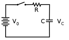
When the switch is first closed, the voltage across the capacitor (assumed fully discharged) is zero volts; thus, it first behaves as though it were a short-circuit. Over time, the capacitor voltage will rise to equal battery voltage, ending in a condition where the capacitor behaves as an open-circuit. Current through the circuit is determined by the difference in voltage between the battery and the capacitor divided by the resistance of R.
Thus the voltage of the capacitor at time 0 is
\begin{equation} V_c(0) = 0 \end{equation}Using KCL, the current through the resistor is the same as that of the capacitor
\begin{equation} {V_o - V_c(t) \over R} = {C {dV_c(t) \over dt}} \end{equation}Rearranging the equation we obtain the following differential equation
\begin{equation} {dV_c(t) \over dt} + {V_c(t) \over RC} - {V_o \over RC} = 0 \end{equation}This differential equation has 3 terms, the first derivative of a function, the function itself (with a constant as multiplier) and a constant. The general solution to this type of differential equation has the following form
\begin{equation} V_c(t) = K_1 e ^ {-{t \over RC}} + K_2 \end{equation}where K1 and K2 are constants. To solve for the constants, first we substitute Vc at time 0
\begin{align} V_c(0) = K_1 + K_2 &= 0 \\ K_1 &= - K_2 \end{align}We rewrite eq 5 in terms of K2
\begin{equation} V_c(t) = K_2 ( 1 - e ^ {-{t \over RC}}) \end{equation}
At time infinity, Vc is charged to Vo. The exponent term also tends to 0, allowing for us to solve for K2
\begin{align} V_c(\infty) = K_2 ( 1 - 0 ) &= V_o \\ K_2 &= V_o \end{align}
And we arrive at the voltage of the capacitor
\begin{equation} V_c(t) = V_o ( 1 - e ^ {-{t \over RC}}) \end{equation}Using the same steps, the voltage of a discharging capacitor initially charged at Vo is
\begin{equation} V_c(t) = V_o e ^ {-{t \over RC}} \end{equation}From eq 9 and 10, we can obtain a universal time constant formula for both charging and discharging
\begin{equation} change = (f-s)( 1 - e ^ {-{t \over RC}}) \end{equation}- where
- change is the capacitor voltage change
- f is the capacitor voltage at infinity
- s is the initial voltage of the capacitor
Capacitors in AC circuits
We can use Ohm's law to describe the relationship of voltage vs current for a capacitor in an AC circuit. Instead of R (resistance) we use (Z) impedance
\begin{equation} V = IZ \end{equation}Impedance, the vector sum of reactance and resistance, describes the phase difference and the ratio of amplitudes between sinusoidally varying voltage and sinusoidally varying current at a given frequency. The reactance (X) and impedance (Z) of a capacitor are respectively
\begin{equation} X = -{1 \over {\omega C}} = -{1 \over { 2\pi fC}} \end{equation} \begin{equation} Z = -{1 \over {j\omega C}} = -{j \over {\omega C}} = -{j \over { 2\pi fC}} \end{equation}where j is the imaginary unit and ω and f is the angular frequency and frequency respectively of the sinusoidal signal. The −j phase indicates that the AC voltage V lags the AC current by 90° unlike the resistor where both the V and I are in phase.
Impedance decreases with increasing capacitance and increasing frequency. This implies that a higher-frequency signal or a larger capacitor results in a lower voltage amplitude per current amplitude — an AC "short circuit" or AC coupling. Conversely, for very low frequencies, the reactance will be high, so that a capacitor is nearly an open circuit in AC analysis.
Capacitors in Parallel
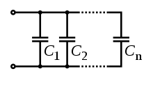
Capacitors in a parallel configuration each have the same applied voltage. Their capacitances add up.
\begin{equation} C_{eq} = C_1 + C_2 + ... + C_n \end{equation}Capacitors in Series
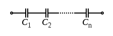
Connected in series, the total voltage difference from end to end is apportioned to each capacitor according to the inverse of its capacitance. The entire series acts as a capacitor smaller than any of its components.
\begin{equation} {1 \over C_{eq}} = {1 \over C_1} + {1 \over C_2} + ... + {1 \over C_n} \end{equation}