JK Flip Flop
The flip flop is a basic building block of sequential logic circuits. It is a circuit that has two stable states and can store one bit of state information. The output changes state by signals applied to one or more control inputs.
The basic JK Flip Flop has J,K inputs and a clock input and outputs Q and Q (the inverse of Q). Optionally it may also include the PR (Preset) and CLR (Clear) control inputs.
The truth table and diagram
The clock input is usually drawn with a triangular input. This flip-flop is a negative edge-triggered flip flop. This means that the flip flop changes output value only when the clock is at a negative edge (or falling clock edge).
- The green switch is a on/off switch (similar to a room light switch). The red switch is a momentary switch (similar to a door bell switch - normally off).
- Q0 is the previous state of Q and Q0 is the previous state of Q.
-
PR and CLR are
asynchronous inputs - that is the output responds to these input immediately. They are active low inputs. Click
on their respective green switches and observe.
- PR presets the output to 1 and CLR clears the output to 0.
- Both PR and CLR cannot be low at the same time - the output is undefined.
- With both PR and CLR
set to high, click on J, K (green), CLK (red) and observe.
- Q depends on the J and K inputs on the falling edge of CLK only when both PR and CLR are high.
- When CLK remains low (or high ie no clock transition), changing the J, K inputs will not affect the Q output (or Q equals to Q0, the previous state).
- J and K are synchronous inputs - ie the output changes only at the presence of clock edge (in this example a falling clock edge).
- By setting both PR and CLR to high, it is identical to a basic JK Flip Flop without these 2 control signals.
- Watch the video to learn how to edit the input (thick) waveforms.
Notes
Applications
2 bit Up / Down Ripple Counter
By connecting the CLK input of the second JK flip flop to Q of the first JK FF, we obtain a 2 bit Up Counter. The output is at both Q of the flip flops. The count sequence for Q1Q0 is 00,01,10,11,00,01 ... where Q1 is the MSB (Most Significant Bit) and Q0 (Least Significant Bit) is the LSB.
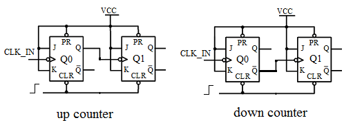
On the other hand, connecting CLK to Q, we obtain a 2 bit Down Counter. The count sequence for Q1Q0 is 00,11,10,01,00,11 ...
When J and K are connected to 1, the JK flip flop is in the toggle mode. By applying low and then high to CLR clears the Q0 and Q1 outputs to 0. By cascading n flip flops, we get a count to 2n counter.
Truncated Ripple Counter
The natural count sequence is to run through all possible combinations of the bit patterns before repeating itself. A Truncated Ripple Counter uses external logic to cause the counter to terminate at a specific count. A decade counter counts from 0 to 9.