Logic Gates, Boolean Algebra and Truth Tables
Boolean Algebra is the mathematical foundation of digital circuits. Boolean Algebra specifies the relationship between Boolean variables which is used to design combinational logic circuits using Logic Gates. The truth table shows a logic circuit's output response to all of the input combinations.
Boolean Algebra
- A Boolean Variable takes the value of either 0 (False) or 1 (True).
- Symbols are used to represent Boolean variables e.g. A, B, C, X, Y, Z
- There are three basic logic operations AND, OR, NOT
- The Boolean Operators are • + ‾
- A + B means A OR B
- A • B means A AND B
- A means NOT A
- Nodes in a circuit are represented by Boolean Variables
A practical use of Boolean algebra is to simplify Boolean expressions which means less logic gates are used to implement the combinational logic circuit.
Logic Gates
Logic gates are electronic circuits that implement the basic functions of Boolean Algebra. There is a symbol for each gate.
Truth Table
The Truth Table shows the values of the circuit output for all input values.
Examples
Boolean Expression Gate Symbol Truth TableLogic levels (0 or 1) are represented by means of a voltage level
- High voltage (5V, 3.3V, 2.5 V, etc.) is 1
- Low voltage (0V) is 0
Equivalent Circuits
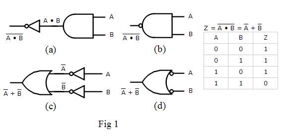
Fig 1 is an example of four circuits that are equivalent because their truth tables are identical.

- (a) is a NOT AND circuit
- (b) is a NAND gate which gets its name from its Not AND configuration. It uses a bubble to represent a NOT gate at its output
- (c) implements the NAND function using OR and NOT gates
- (d) is another way to draw (c) using a bubble to represent a NOT gate at its input
Application of Logic Gates
Logic gates are used to implement the following digital circuit.
Bank Alarm SystemA bank wants to install an alarm system with 3 movement sensors.
To prevent false alarms produced by a single sensor activation, the alarm will be triggered only when at least two sensors activate simultaneously.
Other logic applications like Odd numbers, Multiplexers, Adders, BCD to 7 segment decoder ... which you learn how to use logic gates to implement in minutes!