Combinational Logic Circuits
A combinational logic circuit implement logical functions where its outputs depend only on its current combination of input values. On the other hand sequential circuits, unlike combinational logic, have state or memory.
The main difference between sequential circuits and combinational circuits is that sequential circuits compute their output based on input and state, and that the state is updated based on a clock. Combinational logic circuits implement Boolean functions and are functions only of their inputs.
Representing Combinational Logic Functions
There are 3 ways to represent combinational logic functions
- Logic gates - Logic gates are used as the building blocks in the design of combinational logic circuits. These gates are the AND, OR, NOT, NAND, NOR gates.
- Boolean Algebra - Boolean Algebra specifies the relationship between Boolean variables which is used to design digital circuits using Logic Gates. Every logic circuit can be completely described using the Boolean operations, because the OR, AND gate, and NOT gates are the basic building blocks of digital systems.
- Truth table - A truth table is used in logic to compute the functional values of logical expressions on each combination of values taken by their logical variables. If a combination logic block have more than one bit output, each single-bit output gets its own truth-table. Often they are combined into a single table with multiple output columns, one for each single-bit output.
Combinational Logic Circuit Analysis
To obtain the boolean expressions and truth tables from the combinational logic circuit, we need to analyse the circuit. First ensure that the circuit is combinational - that is there is no feedback of an output to an input that the output depends on.
Boolean Expressions
- label all inputs -- input variables
- label all outputs -- output functions
- label all intermediate signals (outputs that feed inputs)
For each output functions, write it in terms of its input variables and intermediate signals, and then expand intermediate signals until the outputs are expressed only in terms of the inputs.
Truth tables
The truth table can be derived from the Boolean expressions, or by directly working out from the circuit, the outputs for each possible combination of inputs.
If there are n input variables
- there are 2n possible binary input combinations
- there are 2n entries in the truth table for each output
From the examples below, change the inputs to observe the outputs.
Example Circuits
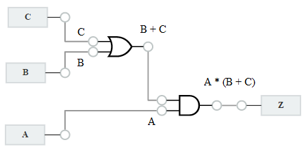
Alarm Circuit
- C : Door Open Sensor
- B : Motion Sensor
- A : Arm Alarm
- Z : Alarm
Half Adder
- A, B : 1 bit inputs
- S : Sum
- C : Carry
Combinational Logic Circuit Design
You have learnt how to obtain the boolean expressions and truth tables from the logic circuits. Next you will learn, using Guided Worked Examples, how to design combinational logic circuits in minutes.
Combinational logic circuits design comprises the following steps
- From the design specification, obtain the truth table
- From the truth table, derive the Sum of Products Boolean Expression.
- Use Karnaugh Map to minimise the boolean expression. The simpler the boolean expression, the less logic gates will be used.
- Use logic gates to implement the simplified Boolean Expression.