Differential Amplifier
A differential amplifier is a type of electronic amplifier that amplifies the difference between two input voltages only. The differential amplifier two inputs are the inverting input and non-inverting input. Its output signal is 180° out of phase with inverting input signal and in phase with non-inverting input signal. It is used in an Operational Amplifier (OPAMP).
The different modes of operation of the differential amplifier are:
- Common mode input signal vCM. Both inputs are connected together to the input signal.
- Large differential input signal.
- Small differential input signal vi<2vT
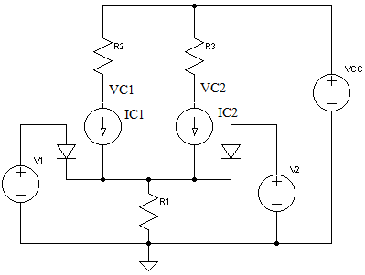
The circuit below shows the differential amplifier with a small differential input signal.

DC Analysis
To perform the DC analysis, we need to redraw the schematic by replacing the transistors with its BJT DC model.
The voltage across R1, VR1 can be calculated using KVL
\begin{equation} V_1 = V_{R1} + V_{BE} \end{equation}Ignoring IB, assuming circuit symmetry and using KCL, the DC collector current IC is half the current through R1.
\begin{equation} I_C = I_E = {V_1 - V_{BE} \over 2 R_1} \end{equation}The DC collector voltage VC1 (wrt GND and not to VE) can be calculated using KVL
\begin{equation} V_{CC} = V_{C1} + I_C R_2 \end{equation}AC Analysis
Similarly for the AC analysis, we need to redraw the schematic by replacing the transistors with its small signal model.
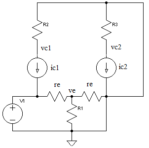
For the AC analysis, calculate re using IE from the DC analysis and vT=26 mV. Note that the AC analysis is only valid for vbe < vT
\begin{equation} r_e = {v_{T} \over I_E} \end{equation}To simplify the calculation of the amplifier gain, we assume the following
- R1 which is parallel to re can be ignored if \begin{equation} R_1 > 10r_e \end{equation}
- The current ic1 = ire = -ic2 (KCL)
The output voltages at VC1 (inverting) and VC2 (non-inverting) are
\begin{align} v_{C1} &= {- {R_2 \over {2r_e}}v_1 } \\ v_{C2} &= {R_3 \over {2r_e}}v_1 \end{align}Finally, the voltage at ve is a simple voltage divider of 2 re
\begin{equation} v_e = {v_1 \over 2} \end{equation}