Synchronous Counter Design
A finite-state machine determines its outputs and its next state from its current inputs and current state. A synchronous finite state machine changes state only when the appropriate clock edge occurs.
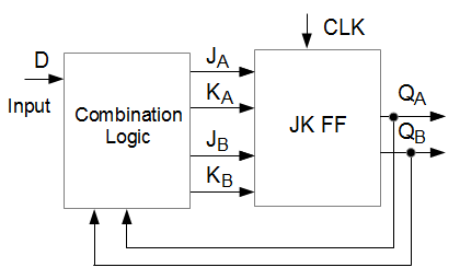
The following diagram shows a sequential circuit that consists of a combinational logic block and a memory block. For simplicity, we limit the design to one input and 2 JK flip flops. You will learn to derive the combination logic that meets the design specifications.
The steps to design a Synchronous Counter using JK flip flops are:
1. Description
Describe a general sequential circuit in terms of its basic parts and its input and outputs.
2. State Diagram
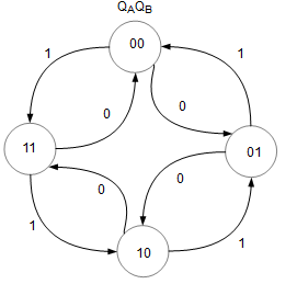
Draw the state diagram for the given sequence.
3. Next State table
Develop a next-state table for the specific counter sequence. Using the state diagram as a reference, fill up the present state and next state (yellow) columns.
For this interactive table, you can modify the next state. After you have changed the values, press the Calculate button. Press the Reset button to reset the page to the initial data.4. FF transition table
Next, the FF transition table (blue) is completed using data from the respective present state, next state and the JK flip flop transition table below. Click on any blue cell to understand how its value is obtained.
The JK flip flop truth table is not required in the design procedure but has been included to explain how the JK flip flop transition table is obtained. Click on any green cell of the JK flip flop transition table to learn how its value has been derived.
5. K Map
Use K-map to derive the boolean expression.
6. Boolean Expression
Use the boolean expressions to implement the counter.
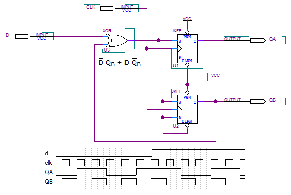 Simulate and Breadboard the Up Down Counter circuit.