Schmitt Trigger Oscillator
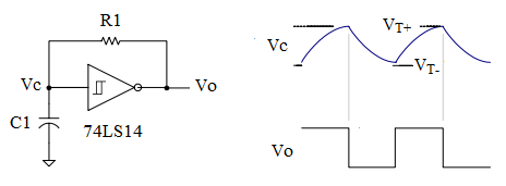
The circuit shown below is a Schmitt trigger RC oscillator using a digital Schmitt trigger inverter gate. The digital Schmitt trigger gate has a built-in hysteresis (0.8V) and the threshold voltages are VT+ (1.6V) and VT- (0.8V). R1 connects the circuit in a positive feedback loop necessary for oscillation.
- When the Vc is less than VT-, Vo goes high (3.4V) and starts charging the capacitor C1 through R1.
- When Vc crosses the threshold voltage VT+, Vo goes low (0.2V) and discharging of C1 through R1 begins.
- When Vc crosses the threshold voltage VT-, step 1 is repeated. Thus the oscillating output is created.
Voltages are the typical values given by the 74LS14 specification.
Using the 74LS14, the output frequency is given by the following equation
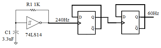
\begin{equation} f_o = {0.8 \over R_1 C_1} \end{equation}Using the values R1 = 1KΩ and C1 = 3.3μF (3300nF)
\begin{equation} \begin{split} f_o & = {0.8 \over 1 \times 10^3 \times 3.3 \times 10^{-6}} \\ & = 242 Hz \end{split} \end{equation}Application
To get an approximate 60Hz clock, add a Divide-by-4 Ripple Counter at the output of this Schmitt trigger RC oscillator.
By adding a divide by 16 and then a divide by 15 counter (divide by 240, 16*15=240), you can obtain a 1Hz clock frequency. Please go to truncated ripple counter to learn how to implement these counters.
Circuit Analysis
To derive the frequency equation of a 74LS14 schmitt trigger oscillator, we will make use of the universal time constant formula for the RC circuit.
\begin{equation} change = (f-s)( 1 - e ^ {-{t \over RC}}) \end{equation}- where
- change is the capacitor voltage change
- f is the capacitor voltage at infinity
- s is the initial voltage of the capacitor
For th (the period when output is high), the capacitor is charged from 0.8V to 1.6V through the resistor from an output of 3.4V. Thus
- Change = 0.8V
- Start = 0.8V
- Final = 3.4V
For tl (the period when output is low), the capacitor is discharged from 1.6V to 0.8V through the resistor from an output of 0.2V. Thus
- Change = -0.8V
- Start = 1.6V
- Final = 0.2V
Total period of the output is
\begin{equation} \begin{split} t &= t_l + t_h \\ &= ( 0.85 + 0.37 ) RC \\ &= 1.22 RC \\ &= {RC \over 0.82} \end{split} \end{equation}And after rounding down the constant, the frequency is
\begin{equation} f = {1 \over t} = {0.8 \over RC} \end{equation}