Wheatstone Bridge Circuit
The basic Wheatstone bridge circuit consists of two arms composed of two resistors in series. A source of excitation (voltage or current) is connected and the output is the difference between the outputs of the two voltage dividers. The Wheatstone bridge circuit is useful for measuring small changes in resistance like that of the strain gauge where typically less than 1% change occurs.
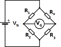
The voltage output of the wheatstone bridge VG is given by
\begin{equation} V_G = V_S ({R_3 \over {R_3 + R_X}} - {R_2 \over {R_1 + R_2}}) \end{equation} \begin{equation} V_G = -V_S [{{R_X R_2 - R_1 R_3} \over {(R_1 + R_2)(R_3 + R_X)}}] \end{equation}If the bridge is balanced VG = 0 since all the resistances are equal. When a change is applied to RX , RX becomes R + ΔR and substituting R to all the other resistances, the change in output voltage ΔVG is
\begin{equation} ΔV_G = -V_S [{ΔR \over {4R + 2ΔR}}] \end{equation}