Current to Voltage Converter
A current to voltage converter will produce a voltage proportional to the given current. This circuit is required if your measuring instrument is capable only of measuring voltages and you need to measure the current output.
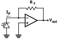
If your instrument or data acquisition module (DAQ) has a input impedance that is several orders larger than the converting resistor, a simple resistor circuit can be used to do the conversion. However, if the input impedance of your instrument is low compared to the converting resistor then the following opamp circuit should be used.
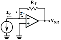
To analyse the current to voltage converter by inspection,
- if we apply KCL to the node at V- (the inverting input) and let the input current to the inverting input be I-, then \begin{equation} {{V_{out} - V_-} \over R_f }= I_p + I_- \end{equation}
- since the output is connected to V- through Rf, the opamp is in a negative feedback configuration. Thus \begin{equation} V_- = V_+ = 0 \end{equation}
- and assuming that I- is 0 and simplifying, \begin{equation} V_{out} = I_pR_f \end{equation}
One example of such an application is using the photodiode sensor to measure light intensity. The output of the photodiode sensor is a current which changes proportional to the light intensity. Another advantage of the opamp circuit is that the voltage across the photodiode (current source) is kept constant at 0V.