D Flip Flop
The flip flop is a basic building block of sequential logic circuits. It is a circuit that has two stable states and can store one bit of state information. The output changes state by signals applied to one or more control inputs.
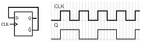
The basic D Flip Flop has a D (data) input and a clock input and outputs Q and Q (the inverse of Q). Optionally it may also include the PR (Preset) and CLR (Clear) control inputs.
The truth table and diagram
The clock input is usually drawn with a triangular input. This flip-flop is a positive edge-triggered flip flop. This means that the flip flop changes output value only when the clock is at a positive edge (or rising clock edge). There is also a negative edge triggered flip flop, which changes on a negative clock edge (or falling clock edge).
- The green switch is a on/off switch (similar to a room light switch). The red switch is a momentary switch (similar to a door bell switch - normally off).
- Q0 is the previous state of Q and Q0 is the previous state of Q.
-
PR and CLR are
asynchronous inputs - that is the output responds to these input immediately. They are active low inputs. Click
on their respective green switches and observe.
- PR presets the output to 1 and CLR clears the output to 0.
- Both PR and CLR cannot be low at the same time - the output is undefined.
- With both PR and CLR
set to high, click on D (green), CLK (red) and observe.
- Q follows D on the rising edge of CLK only when both PR and CLR are high.
- When CLK remains low (or high ie no clock transition), changing the D input does not affect the Q output (or Q equals to Q0, the previous state).
- D is a synchronous input - ie the output changes only at the presence of clock edge (in this example a rising clock edge).
- By setting both PR and CLR to high, it is identical to a basic D Flip Flop without these 2 control signals.
- Watch the video to learn how to edit the input (thick) waveforms.
Notes
- Q output is now 0. What are the two ways the Q output can be changed to 1?
- PR is 0. D is 0. CLK has a rising clock edge. Why does Q output not follow D and change to 0?
FAQ
Applications
Divide-by-4 Ripple Counter - By connecting D to Q, we obtain a divide by 2 counter. The frequency at the output Q compared to the input clock CLK frequency is divided by two. Using 2 flip flops, a divide-by-4 ripple counter is obtained. By cascading n flip flops, we get a divide by 2n counter.
Ring Counter - A ring counter is a Shift Register (a cascade connection of flip-flops) with the output of the last flip flop connected to the input of the first.
Johnson Counter - A Johnson counter is a modified ring counter, where the inverted output from the last flip flop is connected to the input to the first.