Op Amp
An operational amplifier (op-amp) is a DC-coupled high-gain electronic voltage amplifier with a differential input and typically a single-ended output. The output voltage an op-amp produces is typically hundreds of thousands of times larger than the voltage difference between its input terminals.
Characteristics of a circuit using an op-amp are set by external components with little dependence on temperature changes or manufacturing variations in the op-amp itself, which makes op-amps popular building blocks for circuit design.
The operational amplifier is one of the most useful and important components of analog electronics. Op-amps are widely used in consumer, industrial, and scientific devices.
Op Amp Symbol

The circuit symbol for an op-amp is shown to the right, where:
- V+: non-inverting input
- V−: inverting input
- Vout: output
- VS+: positive power supply
- VS−: negative power supply
The amplifier's differential inputs consist of a V+ input and a V− input, and the op-amp amplifies only the difference in voltage between the two, which is called the differential input voltage. The output voltage of the op-amp is given by the equation: \begin{equation} V_{out} = {A_{OL} \, (V_{\!+} - V_{\!-})} \end{equation} where
- V+ is the voltage at the non-inverting terminal, V− is the voltage at the inverting terminal and AOL is the open-loop gain of the amplifier.
- The Vout voltage range is limited by the power supply voltages to VS+ and VS-.
Ideal Op Amp Characteristics
To simplify our calculation of the various practical op-amp configurations, we assume an ideal op-amp which have the following properties:
- Infinite open-loop gain (AOL = ∞)
- voltage range at the output is limited by the power supply voltages to maximum VS+ and minimum VS-. If VS+ and VS- are not specified, then the output voltage range is assumed to be infinite.
- Infinite bandwidth with zero phase shift and infinite slew rate
- Infinite input impedance and so zero input current (I- = I+ = 0)
- Zero input offset voltage
- Zero output impedance
- Zero noise
- Infinite Common-mode rejection ratio (CMRR)
- Infinite Power supply rejection ratio.
Feedback Configurations
Op amps circuits have the following 3 feedback configurations
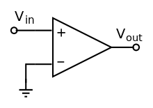
- Open Loop - there is no feedback. An opamp used in this configuration is also called a comparator.
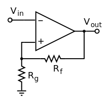
- Negative Feedback - a fraction of the output signal is connected back to the inverting input (V-). Circuits using this configuration are considered linear op-amp circuits and includes
- Inverting, non-inverting, summing, difference
- Instrumentation amplfier
- I-V converter, V-I converter
- Active RC filters, Integrator, Differentiator
For negative feedback circuits only, we can assume the following (why?) \begin{equation} V_+ = V_- \end{equation}
- Positive Feedback - a fraction of the output signal is connected back to the non-inverting input (V+). Circuits using this configuration includes
- Schmitt Trigger
- Schmitt Trigger Oscillator