State Reduction (State Minimization)
By reducing or minimising the total number of states, the number of flip-flops required for a design is also reduced. For example if a finite state machine drops from 8 states to 4 states, only two flip-flops are required rather than three. The total number of states is reduced by eliminating the equivalent states.
Two states are equivalent if they have the same output for all inputs, and if they transition to equivalent states on all inputs.
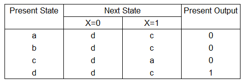
- Comparing states a and b [a,b], we can see that the outputs are the same 0->0 and the next states when X=0 is d->d (d=d), when X=1 is c->c (c=c). Therefore the states a and b are equivalent and one is redundant and can be eliminated.
- Comparing states a and c [a,c], we can see that the outputs are the same 0->0 and the next states when X=0 is d->d (d=d), when X=1 is c->a. For c->a, as the states are referring to each other (we are comparing states a and c), we can ignore this. Therefore the states a and c are equivalent and one can be eliminated.
- Comparing state a and d [a,d], we can see that the outputs are different 0->1. Therefore we can conclude that the states a and d are NOT equivalent. No further checks are required.
- In the end, the 4 states a,b,c,d can be reduced to 2 a,d and the number of flip flops required for this design is reduced from 2 to 1.
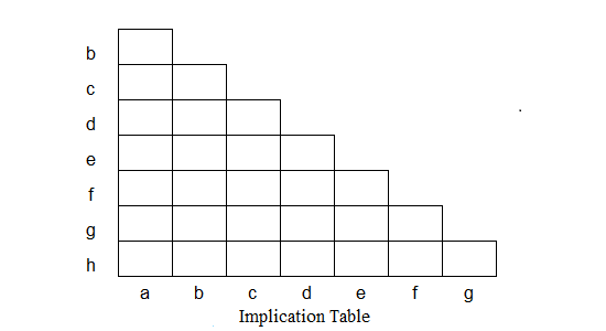
State Reduction using the Implication Table
One method to eliminate the redundant states is to use an implication table. Using the implication table involves the following steps:
- First we need the next state table.
- Draw the blank implication table so that it contains a square for each pair of states in the next state table. For the rows' labels, use the last n-1 states (b to h) where n (8) is the number of states. For the columns' labels, use the first n-1 states (a to g).
- Goto every square in the implication table so that you compare each pair of rows in the state table (up to 3
examples are shown)
- If any of the outputs for the rows being compared differ, place an X in the square.
- If the outputs are the same, list the implied pairs in the square. Any implied pair that is identical (eg c=c) or the states themselves is omitted.
- If the outputs are the same and if both the implied pairs are identical and/or the states themselves (eg [a,g] g=a), then place a ✓ in the square.
- For all squares in the table with implied pairs, examine the square of each implied pair. If any of the implied pair squares has an X, then put an X in this square
- If any Xs were added in step 4, repeat the step 4 until no more Xs are added. Use the left/right arrows on the implication table to observe the steps.
- Upon completion of the previous step, squares without X's indicate equivalent states.
fig 1: Next State Table
This is an interactive Implication Table. You can change the Next State and Present Output of the Next State Table. Press the Calculate button to re-evaluate the Implication Table using your modified values
With the reduced states, proceed to design your synchronous circuit.